Part of:Network cabling types, installation and management tips
What are the different types of network cables?
The main types of network cables are coax, fiber optics, and shielded and unshielded twisted pair. As enterprises deploy new technologies, it's critical to select the right cables.
Selecting cables is a crucial part of network design. Required data rate, cost and distance all dictate the range of choices for each connection. Some connections require an obvious cable option. But others can choose from a range of possible selections.
Network services, like file sharing, internet access, printing and email, are all delivered to end users via the network infrastructure. That infrastructure usually includes switches, routers and -- underpinning it all -- network cabling, one of the oldest and most essential components of network architecture.
A quick history of network cables
Digital communication is not exactly a new idea. In 1844, Samuel Morse sent a message 37 miles -- from Washington, D.C., to Baltimore -- using his invention, the telegraph. This may seem like a far cry from current computer networks, but the principles are the same.
Morse code is a type of binary system that uses dots and dashes in different sequences to represent letters and numbers. Modern data networks use ones and zeros to achieve the same result.
The big difference between now and then is the speed at which data is transmitted. Telegraph operators of the mid-19th century could transmit perhaps four or five dots and dashes per second. Computers can now communicate at speeds of up to 100 Gbps -- or, put another way, 100,000,000,000 separate ones and zeros every second.
Although the telegraph and teletypewriter were the forerunners of data communications, computers advanced with ever-increasing speeds. That advancement drove the development of faster networking equipment. In the process, higher-specification cables and connecting hardware were required.
Let's review the major types of network cabling and the different options available with those cables.
1. Coaxial cable
Coaxial cable, or coax, is one option for network cabling. An inner conductive core is surrounded by a conductive, shielding layer. This shielding layer is then surrounded by an outer protective layer.
The core that carries the signals is solid copper, copper-shielded steel cable or braided copper. Core and conductive shields operate in differential mode to prevent both the emission of electromagnetic interference and the intrusion of external interference.
Coax has a long history. In the mid-19th century, it was used for undersea cabling. Today, it is used in a wide range of applications, including residential broadband, telephone lines, and connections to radio and TV broadcasters.
Within data centers, coax is often used for fiber channel connections between servers and disk drives. Its resistance to electrical noise makes it valuable in noisy environments, such as industrial facilities.
Development of Ethernet
The first Ethernet standard used coax cabling. Ethernet was developed in the mid-1970s by Robert Metcalfe and David Boggs at Xerox's Palo Alto Research Center in California. In 1979, Digital Equipment Corp. and Intel joined forces with Xerox to standardize the Ethernet system. The first specification by the three companies, called Ethernet Blue Book, was released in 1980. It was also known as the DIX standard, after the companies' initials.
That standard called for speeds of up to 10 Mbps -- 10 Mbps equals 10 million ones and zeros per second. The Ethernet standard relied on a large coax backbone cable running throughout the building, with smaller coax cables tapped off at 2.5 meter (m) intervals to connect to the workstations. The larger coax, which was usually yellow, became known as Thick Ethernet, or 10Base-5.
Below is a breakdown of the 10Base-5 term:
10 refers to the speed -- 10 Mbps.
Base refers to the baseband system. Baseband uses all its bandwidth for each transmission. In contrast, broadband splits the bandwidth into separate channels to use concurrently.
5 refers to the system's maximum cable length -- in this case, 500 m.
In 1983, the Institute of Electrical and Electronics Engineers (IEEE) released the official Ethernet standard. It was called IEEE 802.3, after the name of the working group responsible for its development.
Version 2, IEEE 802.3a, was released in 1985. This second version is commonly known as Thin Ethernet, or 10Base-2. In this version, the maximum length is 185 m, even though the 2 suggests it should be 200 m. Since 1985, various Ethernet standards have been introduced.
Twinax cable
Twinax cable is similar to coax, but instead of a single core, the twinax core consists of two wires. Twinax carries high data rate Ethernet at a lower cost than fiber.
Passive twinax supports short-distance connections. Active twinax includes components that boost signal strength, which enables longer-distance connections.
Triax and quadrax cables
Triax and quadrax cables are also similar to coax. They are most often used for TV connections but can also carry Gigabit Ethernet.
The triax core is similar to coax, but it has an additional insulation layer and shielding layer. A quadrax core has four individual wires. Both triax and quadrax have the extra insulation and shielding layers, which enables the transmission of additional signals or carrying power.
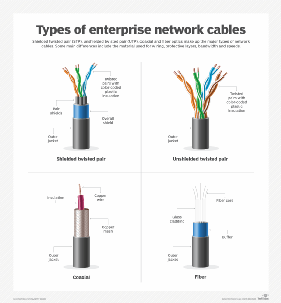
A diagram of the different types of network cables
2. Twisted pair
Originally invented by Alexander Graham Bell to carry telephone signals, twisted-pair cabling is the most common choice for network cabling.
Twisted pair uses copper wires that are, as the name suggests, twisted together in pairs. The twist effect of each pair in the cables ensures any interference presented or picked up on one cable is canceled by the cable's partner that twists around the initial cable. Twisting the two wires also reduces the electromagnetic radiation emitted by the circuit.
In STP, copper wires are first covered by plastic insulation. A metal shield, which consists of metal foil or braid, surrounds the bundle of insulated pairs. Where electromagnetic radiation is a serious issue, each pair of wires may be individually shielded in addition to the outer shield. This is known as foil twisted pair (FTP).
10 Mbps and 100 Mbps use two pairs of cable to transmit Ethernet. Gigabit throughput requires the use of all four pairs.
Unshielded twisted pair
UTP cable is the most popular type of network cable. It is easy to work with, install, expand and troubleshoot. UTP cables typically contain four pairs of copper wires, with each pair containing two wires twisted together. These pairs are covered by plastic insulation. They do not have any shielding and just have an outer jacket.
Most categories of twisted-pair cables are available as UTP. But some newer categories are also available in combinations of shielded, foil shielded and unshielded.
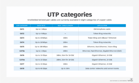
Categories of twisted-pair cables
The American National Standards Institute and the International Electrotechnical Commission, part of the International Organization for Standardization, established a series of standards, or categories, for twisted pair. Category 1, or Cat1, and Cat2 were not officially standardized, but de facto standards developed over time. Eight categories of cables are currently available.
These categories specify the type of copper wire and jacks. The number -- 1, 3, 5 and so on -- refers to the revision of the specification and to the number of twists inside the wire -- i.e., the quality of connection in a jack.
Cat1
Cat1 is typically used for telephone wire and voice communications. This type of wire is not capable of supporting computer network traffic and is not twisted.
Telecom companies can use Cat1 to provide Integrated Services Digital Network and public switched telephone network services. In such cases, the wiring between the customer's site and the telecom operator's network is performed using Cat1-type cable. Cat1 is also now used for some low data rate IoT networks.
Cat2
Cat2 cables are network wire specifications, using four pairs of twisted copper wires. These types of wires can support computer network and telephone traffic. Cat2 is used mostly for token ring networks and supports speeds up to 4 Mbps. For higher network speeds -- 100 Mbps or higher -- Cat5e or higher must be used.
Cat3
Cat3 cables are four pairs of twisted copper wires. Cat3 was used to support the initial 10 Mbps Ethernet, typically for token ring networks. Although 10 Mbps speeds are almost extinct, some deployments still use Cat3.
Use this chart to compare the different categories of twisted pair cables.
Cat4
Cat4 cables are four pairs of twisted copper wires. As with Cat3 cables, Cat4 is used for token ring networks. While Cat3 provides support of a maximum 10 Mbps, Cat4 pushed the limit up to 16 Mbps. Both categories have a length limit of 100 m. Cat4 is not widely used.
Cat5 and Cat5e
Cat5 cables are four pairs of twisted copper wires. Cat5 has more twists per inch than Cat3, so it can run at higher speeds and greater lengths.
The more popular Cat5 wire has largely been replaced by the Cat5e specification. Cat5e provides improved crosstalk specification, enabling it to support speeds of up to 1 Gbps.
UTP-Cat5e is one of the more popular UTP cables. It replaced old coax cables that were unable to keep up with the constantly growing need for faster and more reliable networks. Cat5e is the most widely used type of network cabling specification worldwide and is cost-effective. Unlike the category cables that follow, it is forgiving when cable termination and deployment guidelines are not met.
Cat5 and Cat5e are more widely used for both 10 Mbps and 100 Mbps Ethernet.
Cat6 and Cat6a
Cat6 wire was originally designed to support Gigabit Ethernet, although other standards enable gigabit transmission over Cat5e wire. Cat6 is similar to Cat5e wire, but it contains a physical separator between the four pairs to further reduce electromagnetic interference.
No one type of cable is appropriate everywhere.
Cat6 can support speeds of 1 Gbps for lengths of up to 100 m. It also supports 10 Gbps for lengths of up to 55 m. It uses bandwidth frequencies up to 250 MHz.
When installing new Cat6 cables, it is important to note that all cabling components -- jacks, patch panels, patch cords and the like -- must be Cat6-certified. This requires network pros to be extra cautious about proper termination of the cable ends. Organizations performing installations using Cat6 cabling should request a thorough test report, using a certified cable analyzer, to ensure the installation has been performed according to Cat6 guidelines and standards.
In 2009, Cat6a was introduced as a higher specification cable, offering better immunization from crosstalk and electromagnetic interference. It offers better bandwidth using frequencies up to 500 MHz, supports 10 Gbps and has a cable length up to 100 m.
Cat7
Cat7 is a copper cable specification designed to support speeds of 10 Gbps at lengths of up to 100 m. To achieve this, the cable uses FTP for four individually shielded pairs, plus an additional cable shield to protect the signals from crosstalk and electromagnetic interference.
Due to extremely high data rates, all components used throughout the installation of a Cat7 network cabling infrastructure must be Cat7-certified. This includes patch panels, patch cords, jacks and RJ-45 connectors. The absence of Cat7-certified components will degrade overall performance and lead to the failure of any Cat7 certification tests -- for example, using a cable analyzer -- because Cat7 performance standards are most likely not met.
Cat7 is usually used in data centers for backbone connections among servers, network switches and storage devices.
Cat8
Cat8 is a newer category of twisted-pair cabling that better competes with the speed and scale of fiber optics. It has a maximum data rate of 40 Gbps and uses RJ-45 connectors. It uses the 2 GHz -- or 2,000 MHz -- frequency, an increase from Cat7's 600 MHz.
Cat8 cables are typically used in data center environments. They are backward-compatible with previous standards and support Power over Ethernet (PoE).
PoE eliminates the need to run a separate power wire to devices, such as ceiling-installed access points. For low data rates, PoE cables supply power using the pairs not needed by Ethernet. For higher rates, where all four pairs are used, PoE adds direct current to the wires carrying the signal, without interfering with the signals.
3. Fiber optic cable
Data rates have increased throughout the network, and in some cases, fiber optics is the only option. While Cat8 twisted-pair cables can carry up to 40 Gbps of data, fiber supports data rates up to 400 Gbps. Work is currently underway to test 800 Gbps.
Fiber optic cables consist of a thin optical fiber surrounded by cladding. Cladding is made from glass that is less pure than the core and has a lower refractive index than the core. The difference in refractive indices causes light to be reflected at the boundary. Additional layers, such as the buffer layer and jacket layer, surround the cladding to add strength and protect the cable against damage.
Fiber has a low error rate. Network data is encoded in a light beam. Unlike with twisted-pair cables, the light beam neither generates nor is affected by electronic interference. Additionally, multiple frequency data streams can be multiplexed over a single fiber to increase the total data rate.
Multimode fiber vs. single-mode fiber
Fiber types differ by the diameter of the fiber. Multimode optical fiber ranges from 50 microns to 100 microns (10-4 m). In a single-mode cable, the optical fiber is only 8 microns to 10.5 microns in diameter.
Multimode cable is less expensive to make and install than single mode, but it is limited in data rate and distance. While multimode can carry 100 Gbps for 150 m, single mode can carry 400 Gbps for up to 10 kilometers and lower rates for additional distances.
Performance varies between multimode and single-mode fiber because of how light travels through each. The larger fiber used in multimode causes the light beam to reflect from the fiber and cladding boundary at a steeper angle than the thinner core in single mode. Single mode's thinner core causes the distance between reflections to be smaller. When reflections are more frequent, losses are larger at the boundary.
No choice is permanent
No one type of cable is appropriate everywhere. Supported data rates, installed cost and future adequacy must be considered for each application. Ongoing maintenance costs should also be a factor.
Remember, no choice is permanent. Just as organizations periodically replace servers and workstations, they can reconsider their choice of connection technology for each network upgrade.