Spanning Tree Protocol (STP)

What is STP and how does it work?
Spanning Tree Protocol (STP) is a Layer 2 network protocol used to prevent looping within a network topology. STP was created to avoid the problems that arise when computers exchange data on a local area network (LAN) that contains redundant paths. If the flow of traffic is not carefully monitored and controlled, the data can be caught in a loop that circles around network segments, affecting performance and bringing traffic to a near halt.
Networks are often configured with redundant paths when connecting network segments. Although redundancy can help protect against disaster, it can also lead to bridge or switch looping. Looping occurs when data travels from a source to a destination along redundant paths and the data begins to circle around the same paths, becoming amplified and resulting in a broadcast storm.
STP can help prevent bridge looping on LANs that include redundant links. Without STP, it would be difficult to implement that redundancy and still avoid network looping. STP monitors all network links, identifies redundant connections and disables the ports that can lead to looping.
LANs are often divided into multiple network segments, and they use bridges to connect the individual segment pairs. Each message, called a frame, goes through the bridge before being sent to the intended destination. The bridge determines whether the message is for a destination within the same segment as the sender's or for another segment and then forwards the message accordingly. When used in the context of STP, the term bridge can also refer to a network switch.
A bridge looks at the destination address and, based on its understanding of which computers are on which segments, forwards the data on the right path via the correct outgoing port. Network segmentation and bridging can reduce the amount of competition for a network path by half -- assuming each segment has the same number of computers. As a result, the network is much less likely to come to a halt.
A segmented LAN is often designed with redundant bridges and paths to ensure that communications can continue in the event that a network link becomes unavailable. However, this makes the network more susceptible to looping, so a system must be put into place to prevent this possibility, which is where STP comes in.
When STP is enabled, each bridge learns which computers are on which segment by sending a first-time message to network segments. Through this process, the bridge discovers the computers' locations and records the details in a table. When subsequent messages are sent, the bridge uses the table to determine which segment to forward them to. Enabling the bridge to learn about the network on its own is known as transparent bridging, a process that eliminates the need for an administrator to set up bridging manually.
In a network that contains redundant paths, bridges need to continually understand the topology of the network to control the flow of traffic and prevent looping. To do this, they exchange bridge protocol data units (BPDUs) via an extended LAN that uses a spanning tree protocol. BPDUs are data messages that provide the bridges with network information that's used to carry out STP operations.
At the heart of STP is the spanning tree algorithm that runs on each STP-enabled bridge. The algorithm was specifically designed to avoid bridge loops when redundant paths exist. It uses the BPDUs to identify redundant links and select the best data path for forwarding messages. The algorithm also controls packet forwarding by setting the port state.
What are STP port states?
When STP is enabled on a network bridge, each port is set to one of five states to control frame forwarding:
- Disabled. The port does not participate in frame forwarding or STP operations.
- Blocking. The port does not participate in frame forwarding and discards frames received from the attached network segment. However, the port continues to listen for and process BPDUs.
- Listening. From the blocking state, the port transitions to the listening state. The port discards frames from the attached network segment or forwarded from another port. However, it receives BPDUs and redirects them to the switch module for processing.
- Learning. The port moves from the listening state to the learning state. It listens for and processes BPDUs but discards frames from the attached network segment or forwarded from another port. It also starts updating the address table with the information it's learned. In addition, it processes user frames but does not forward those frames.
- Forwarding. The port moves from the learning state to the forwarding state and starts forwarding frames across the network segments. This includes frames from the attached network segment and those forwarded from another port. The port also continues to receive and process BPDUs, and the address table continues to be updated.
STP moves from the blocking state through the forwarding state in relatively short order, usually between 15 to 20 seconds for each state. Every port starts in the blocking state. If it's been disabled, the port enters directly into the blocking state upon being enabled. STP balances the states across ports to avoid bridge looping, while still making redundancy possible.
What are STP modes?
To understand STP modes, it helps to go back to STP's beginnings. The original spanning tree protocol and algorithm were invented in 1985 by Radia Perlman when she was working at Digital Equipment Corporation. Spanning tree protocols were later standardized by the Institute of Electrical and Electronics Engineers (IEEE). Since then, the protocol has evolved in a number of ways, and new variations have been introduced.
The following table provides an overview of the most common spanning tree protocols. However, not all bridges and switches support every one of these protocols, and there are other spanning tree-inspired protocols not listed here.
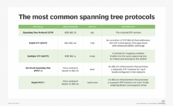
The IEEE standard column shows the standard on which the protocol was originally based. IEEE commonly reorganizes these standards, and it can be confusing to track which standard currently incorporates STP functionality. For example, 802.1D was updated in the 802.1D-2004 revision, which also incorporated 802.1w. After that, the 802.1Q-2014 standard was released, and it included much of the functionality specified in 801.1D.
The Switch column shows the option that should be used to specify the protocol mode when enabling STP on a bridge or switch. To enable STP, a network administrator connects to the device, enters global configuration mode and runs a command in the following format:
spanning-tree mode <protocol mode>
For example, to enable Rapid STP (RSTP) on a switch, the administrator would run the following command:
spanning-tree mode rstp
In addition to enabling STP, an administrator must select a root bridge to serve as the network's central STP reference point. The administrator must also identify root ports and designated ports. A root port is a bridge port that forwards frames to the root bridge, and a designated port is a bridge port that forwards frames away from the root bridge.
Should you enable STP?
STP prevents bridge looping and the broadcast storms that come with it. Once configured, STP automatically disables certain redundant links and determines which links remain enabled. In this way, a network can be configured with redundant data paths that provide failover services to protect against disaster, without the risk of bridge looping.
STP offers several important benefits:
- proven technology;
- easy to implement and maintain;
- wide support for bridges and switches;
- facilitates link redundancy, while simultaneously preventing undesirable loops; and
- supports the use of backups in case the primary data path becomes unavailable.
Despite these benefits, STP is not without its challenges:
- As data centers use more virtualization technologies, STP might not be able to handle the increased input/output demands.
- Full network capacity is not realized when using STP. Even when there are equal-cost multiple paths on a network, all traffic flows along a single path as defined by a spanning tree. This restriction of traffic means alternative, and perhaps more direct, paths are blocked.
Even with these challenges, the benefits of STP usually outweigh the risks. But the STP implementation must be carefully planned and deployed to ensure that it delivers the necessary level of service. In addition, attention should be given to which spanning tree protocol to use, and the same protocol should be implemented throughout the network.
Alternatives to Spanning Tree Protocol
The two main alternatives to STP are Transparent Interconnection of Lots of Links (TRILL) and Shortest Path Bridging (SPB).
Radia Perlman developed TRILL as a way to improve on the spanning tree algorithm. The protocol was then standardized by the Internet Engineering Task Force (IETF). TRILL uses Layer 3 network routing techniques to create a cloud of links that appear to Internet Protocol nodes as a single IP subnet.
TRILL uses shortest path routing protocols and can be used at the same time as STP.
The main benefit of TRILL is that it frees up network capacity. Shortest path routing improves efficiency and decreases the cost-to-benefit ratio. Data centers running a cloud computing infrastructure may choose TRILL because it provides faster recovery time than STP should hardware fail.
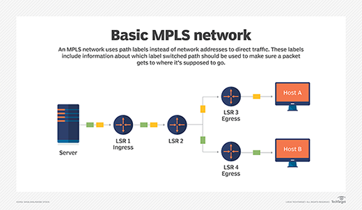
SPB (802.1aq) was codeveloped by IEEE and IETF. SPB combines the effectiveness of Multiprotocol Label Switching (MPLS) with the efficiency of Ethernet. SPB is backward-compatible with STP.